Thursday, July 26, 2012

More Solidworks Parts

Accelerometer: 
The dimensions of the board and pins are estimated; the length and width of the red part (representing the size of the accelerometer) is accurate. All boards are assumed to be somewhere around 1/16in thick. The connector design was based off of a part from the Arduino Mega file. There are also two resistors and some wires soldered onto the perf board but I'm ignoring them in this model.


Barometric Pressure Sensor:
The black connectors are again taken from the Arduino Mega files. Everything else is estimated (on the large side).


Temperature/Humidity Sensor:
Dimensions taken from the datasheet. Some measurements (like the angle of the two slanted cuts and the thickness of the back plate) are estimated. 

Capacitor:
Really rough estimate of dimensions for an 1000 micro-Farad capacitor. 


I'm working on the assembly of the box with all the parts inside tomorrow.

Wednesday, July 25, 2012

Some Solidworks Files

Before making the enclosure, I also need to do a rough modeling of the components that go inside.

I was lucky enough to find an Arduino Mega SolidWorks file online. Although it's not an Mega ADK, the only difference between this and the ADK is that the ADK has a USB port in the middle between the two other ports. The other physical aspects are pretty much the same.


The rest of the components I rendered myself. For many of them, I had to estimate the specs, because I couldn't find the datasheets to go with them online.

Fan: 
The placement of the holes and the size is correct. I did something silly with the fan blades =]


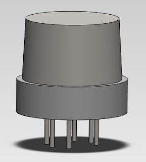
CO Gas Sensor: The maximum height, widest diameter, and the placement and spacing of the pins are correct. I estimated the width of the pins, and the little depression at the top is just for visual effects.


Generic Gas Sensor (For Methane, LPG, Hydrogen): 
The height and widest diameter are correct. Again, I estimated the width of the pins.


Geiger Counter: 
Breakout Board:
This was the most difficult one to model, as I did not have access to any datasheets. I estimated all the dimensions, however I believe the important ones to be correct or at least incredibly close. I left out the capacitors, as they are shorter than the maximum height, and also left out the 4 supports at the corners of the board because I wasn't sure what the dimensions of those were. I will have to figure this out eventually because they are essential when mounting the board.


Geiger Tube:
Again, dimensions are estimated. I rendered the tube without the red cap on.


Optical Dust Sensor:
This one had a very detailed datasheet, so I'm lucky. The only thing I didn't render are the connectors. See original for comparison.


Fan Wall:
This is the wall where the fan will be mounted. Since we didn't buy finger guards for the fans, I will laser cut the circular pattern on Plexiglas and then mill the holes. The holes match the holes on the fan, so it should be easy to mount. 


I will finish up the rest of the renders tomorrow and figure out what kinds of screws/fasteners I will need to put everything together. 

Monday, July 23, 2012

Making the Enclosure

I figured out the physical dimensions for the major components that need to be fit into the project box/enclosure and also drew some really rough *ROUGH* drafts of the box. At this point I'm just playing around with the dimensions to figure out how to make the box as small as possible without making it too cramped. I'm also going to need to go down to the Mech E shop tomorrow and figure out all the nuts and bolts I'm going to need.

Thursday, July 19, 2012

Putting Everything Together: Part 8

Added the code for the BMA180 Accelerometer to the master sketch, and linked everything together. Note: I didn't have the Geiger Counter at this time because I lent it to someone else for testing code but the connection stays the same and should work as before. Behold! The wire forest has grown:


The devices currently attached on the breadboard are: Photocell, Temperature/Humidity sensor, Optical Dust sensor, Temperature/Pressure sensor, and the Accelerometer.The setup for the Geiger Counter (with the big capacitor) is there but the actual Geiger Counter is currently being used by one of the Indian students who are working here over the summer.

Right, I should have mentioned that there are three students from India working here who are currently developing code for reading values from the Arduino to the Android. One of the students helped me set up the Android SDK and Java/Eclipse environment on my computer. He also gave me some code they had been working on, so I should be able to test my devices using an android from this computer as well. (The Arduino must be connected to the computer as well as the Android). 


Wednesday, July 18, 2012

Putting Everything Together Part 7: Accelerometer

Just finished the code for the BMA180 accelerometer today. I rewrote Dr. Bunn's code for the accelerometer into a library. The program will initialize the BMA180 and then output the acceleration felt in the horizontal and vertical axes (AH, AV). Here's a sample of the code (with the accelerometer on the table monitoring natural vibrations):


Reset BMA180 and Init
BMA180 Chip Id = 3
BMA180 Version = 20
Register 0x37 contents (12 bits) = 1101000
Register 0x30 contents (mode config) = 10000000
Register 0x30 will be set to = 10000011
Register 0x30 contents after write = 131
Register 0x20 contents = 1001000
Register 0x20 (bandwidth) contents after write = 1001111
Register 0x35 contents = 11000100
Register 0x35 (range) contents after write = 11000000
BMA180 Init Successful
AH: 0.05  AV: 1.02
AH: 0.05  AV: 1.02
AH: 0.06  AV: 1.02
AH: 0.04  AV: 1.02
AH: 0.05  AV: 1.02
AH: 0.06  AV: 1.02
AH: 0.05  AV: 1.02
AH: 0.06  AV: 1.02
AH: 0.05  AV: 1.02
AH: 0.06  AV: 1.02
AH: 0.05  AV: 1.02
AH: 0.06  AV: 1.02
AH: 0.04  AV: 1.02
AH: 0.06  AV: 1.02
AH: 0.06  AV: 1.02
AH: 0.04  AV: 1.02
AH: 0.05  AV: 1.02
AH: 0.05  AV: 1.02
AH: 0.06  AV: 1.02

The picture of the accelerometer looks like this:


The Fritizing picture looks like this:
Since I didn't want to spend all the time making a custom part for the BMA180, I just used the generic "mystery part". From left to right, the pins on the custom generated BMA180 are: VDD, GND, INT, CS, SCK, SDO, SDI, VIO. These should match the order of the pins on the real model as well.


The blue wire connects to 3.3V pin on the Arduino Duemilanove, the black wires connect to the GND pin, the red wire connects to A4 (SDA) and the orange wire connects to A5 (SCL). Thus, on the Arduino Mega/ADK, we would connect the red wire to pin 20 and the orange wire to pin 21. 

Monday, July 16, 2012

Optical Dust Sensor - Update

As of now, I'm unable to get this sensor to work properly without using the delay() functions. It seems that the amount of time it takes to read data from the sensor is significant enough on the microseconds scale, and so gives me strange readings. I'm using the delayMicroseconds() function to turn the LED in the sensor on and off.

The code is pretty much exactly the same as from here, but wrapped inside a library. I control the time delay between each reading from the master sketch that I will upload to the Arduino once I figure out all the components.

I might return to figure this out without using delay(). The Arduino webpage for the delay function says that it's common to use delay for processes that take only 10's of milliseconds, so using delay() isn't a huge issue right now.

The final sensor I need to include in my prototype is the Accelerometer, which I will start writing a library for now. If I have time, I might also figure out the microphone, but half of SURF is already over and I need to start working on the Android interface and the actual box design...

Thursday, July 12, 2012

Putting Everything Together: Part 4: Random Progress + Optical Dust Sensor Code

Before I start, I just want to mention that I figured out that the BMP Pressure sensor needs have the SCL wire attached to the SCL pin on the Arduino Mega/ADK, and the SDA wire attached to the SDA pin. I guess they were pins 5 and 4 on the Duemilanove, but the Mega/ADK have specifically labeled their pins 20-21 with the SCL/SDA labels. Yes, now it seems trivial, but when the code/examples only told you to "put these wires into pins 4 and 5", it sometimes is a bit hard to figure out everything when so many things can go wrong.

So, now the BMP Pressure Sensor works on the ADK and Mega just like it did on the Duemilanove. :D


Anyways, on Wednesday I also wrote code for running a bunch of sensors together simultaneously, much like what I did for the gas sensors. The sensors include the BMP Pressure Sensor, Temperature/Humidity Sensor, and the Geiger Counter.

Below is a picture of the setup:


Notice that I also wired in the optical dust sensor, which I worked on today.


Optical Dust Sensor

The optical dust sensor works pretty interestingly. The physical setup, for reference, looks like this. The code for it requires that an LED inside the sensor turns on and off during a 10ms cycle:

-Turn on LED for 280µs
-Take reading
-Wait 40µs
-Turn off for 9680µs

So the maximum sampling rate is 1sample/10ms. The original code was simple enough; however, turning this into a library is proving surprisingly difficult, and at the end of the day, I'm still not done. 


This is when I learned about time limits. A microsecond is a really, really short amount of time. Short enough, in fact, that the time it takes to transmit data is significant. Though we are not sure, it seems that the sensor might not be able to read data in time when the code becomes more complicated (and hence takes longer to run through). 

The original way I tried to convert the .ino file into a .cpp library was to use the modulus operator % to get the "stage" of the cycle time, and then determine what to do based on the stage. I've also tried running while loops with the code, but so far, I can't get a reading. Guess I'll keep trying tomorrow. 

Tuesday, July 10, 2012

Putting Everything Together: Part 3: Barometric Pressure Sensor

Last week, as I was also working on the BMP085 Barometric Pressure/Temperature Sensor. As this sensor came with calibration values issued by the factory, it was a bit harder to set up. It also seems to have some compatibility issues with the Arduino Mega ADK/Arduino Mega, where as it did not seem to have any problem with the Arduino Duemilanove.**


Though we also have a temperature/humidity sensor, it's a good check to have a temperature sensor on this one as well. Temperature on this one is measured in ... uh... deci-degrees C? That is, the number 277 means 27.7 degrees, which is actually rather uncomfortably warm for my room. Barometric pressure is measured in Pa.

Here's an example of the readout:

Temperature: 277 * 0.1 deg C
Pressure: 98218 Pa


Temperature: 277 * 0.1 deg C
Pressure: 98218 Pa


Temperature: 277 * 0.1 deg C
Pressure: 98221 Pa


Temperature: 277 * 0.1 deg C
Pressure: 98224 Pa


Temperature: 277 * 0.1 deg C
Pressure: 98224 Pa


The current output is 1 reading/second, though that can be easily changed.

**It seems that the Arduino Mega/Mega ADK both have trouble reading the calibration values from the device at certain times. The Duemilanove has no such issue and is always able to display data on the terminal. The Mega/Mega ADK sometimes gets "stuck".

Friday, July 6, 2012

Putting Everything Together: Part 2: Geiger Counter

So.... putting everything together proved rather tough for the other sensors that requires more complex code.   As I'm not that familiar with C++ (I tend to code in Java/Python) and the use of libraries, I had to read up on how everything worked first. This took a good half of the week, as there were little nuances that kept cropping up whenever I tried to turn the files for reading the BMP085 Pressure/Temperature sensor or the Geiger Counter into libraries. Anyways, today's post is about the Geiger Counter.

The setup with the GeigerCounter looks like this (on the Arduino Mega ADK):


The code (not sure if I should post complete code, since it's technically not mine...?) roughly works like this:

The GeigerCounter.ino file will read input from the sensor continuously. Functions are stored in a header (.h) and source (.cpp) file. Whenever the counter registers a "pick" (a particle hitting the Geiger Tube) an LED on the breakout board that came with the tube will light up. This will prompt the GeigerCounter's computePick() to print out the average rate, the average time gap between each particle hit (in ms), and so on.

We also output the average rate continuously in order to send a stream of data to the cloud. There are also functions that lets us output other useful measurements, such as gap, standard deviation, etc. We will determine later on what specific data we want to transmit.

Having the ability to send "picks" will be useful for the average user, who will probably only want to know when something important is happening. The continuous transmission to the cloud will be useful for scientists/researchers who will need more data.